Conceptual Graphs (WS 2017 /2018)
Contents
History
Conceptual Graphs (CG, www.conceptualgraphs.org) are one of the semantic text models related to the semantic networks. Conceptual graphs were proposed in J. Sova's works and now play an important role as a means of modeling structures in such areas as mathematical linguistics, bioinformatics, mathematical logic and artificial intelligence. CG model was considered as a compromise between a formal language and a graphical language. History Graph-based semantic depiction was extremely popular in both computational and theoretical linguistics during the 1960s. In the early 1960s a semantic network including a lattice of concept types was introduced by Margaret Masterman. A bit later, Silvio Ceccato came up with correlational nets based on 56 different relations with subtypes, instances and many kinds of attributes. David Hays followed with his presentation of dependency graphs. Although all these graph notations represented the relational structure semantics, none of them could express full first-order logic. In 1970s many graph notations were introduced to represent first-order logic or a formally defined subset. In 1976 John F. Sowa developed his version of conceptual graphs (CGs). He emphasized by CG syntax the features of natural language and based their logical structure on existential graphs (EG) of Charles Sanders Peirce (1909).
The difference between the EG and CG notations
Pierce used three operators to visualize the first-order logic (FOL) using existential graphs (EG). These operators are: • an existential quantifier expressed by a bar or linked structure of bars called a line of identity; • negation expressed by an oval context delimiter; • conjunction expressed by the occurrence of two or more graphs in the same context. Sowa in his CGs has used rectangles, which are called concepts and linked concepts with ovals, which are called conceptual relations. Conceptual graphs are usually presented in the following form, also called a display form:
Figure 1. CG Display Form
This display form is read as “ConceptB represents the relation of ConceptA”, where arrows direction points out the direction of the display form reading. The display form shown on the figure 1 can be translated into text based form, also known as linear form:
The full stop in this linear form indicates the end of the certain graph. Admittedly, concepts can have referents referring to an instance or person of the concept. As an example, to create the type label ‘Student’ and assign referent to it, let’s say, Laura, the concept would look like:
This concept is read as “The Student known as Laura”, where Laura is a conformity to the type label Student in the given concept. In other words, Laura conforms to the label Student.
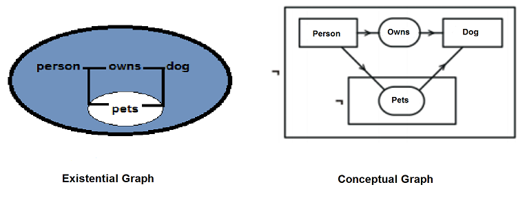
Figure 2 visualizes the difference between the EG and CG. Both kinds of graphs describe the sentence “ If a person owns a dog then he pets it”.
Figure 2. Existential and Conceptual Graphs
In EG an oval enclosure shows scope and the default operator for oval with no other marking is negation, but any metalevel relation can be linked to the oval. For CGs, Sowa used rectangles instead of ovals as rectangles nest better than ovals; and more importantly, each context box can be interpreted as a concept box that contains a nested CG. In the given example, there is an arrow or an arc that is directed toward an oval and identifies the first argument of the relation. An arrow that is directed away from an oval marks the last argument. The sentence “if a person owns a dog then he pets it” can also be represented by the following linear formula:
All the model-theoretic semantics in the CGs and EGs are specified in the ISO standard for Common Logic (CL). Graphs semantic features represented using linear notations are called the Conceptual Graph Interchange Format (CGIF). There two types of the CGIF:
* Core CGIF
This represents a type of logic without a type and expresses the full Common Logic semantics.This mostly corresponds to Peirce’s EGs: its only primitives are conjunction, negation, and the existential quantifier. It does permit quantifiers to range over relations, but Peirce also experimented with that option for EGs.
*Extended CGIF
This represents an upward compatible extension of the core and adds a universal quantifier; type labels for restricting the range of quantifiers; Boolean contexts with type labels If, Then, Either, Or, Equivalence, and Iff; and the option of importing external text into any CGIF text.
Canonical formation rules
Sowa has identified six canonical formation rules, which represent examples of graph-based operators that focus on the semantics. There exist also combinations of the formation rules. These combinations are called projection and maximal join. They give the ability for the larger semantic operations, for example questioning, answering or comparison of alternatives.
Equivalence
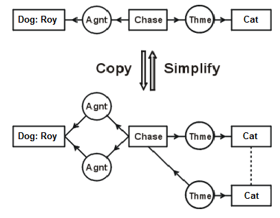
Rules that generate a certain graph v, which is logically equivalent to the original graph u in such a way that u ⊃ v and v ⊃ u, are generated by equivalence rules copy and simplify. Exactly the same models contain equivalent graphs.
Example
The conceptual graph at the picture represents the sentence The dog Roy is chasing a cat. The arrow that is directed down denotes two applications of the copy rule. One application copies the Agnt relation, and a second copies the subgraph →(Thme)→[Cat]. The link that connects both [Cat] concepts shows that these concepts refer to the same individual. The arrow that is directed up denotes two applications of the simplify rule. Simplify rule makes the inverse operations of removing unnecessary copies.
Figure 3. Copy and Simplify
CGIF sentences for EG and CG graphs will look like:
Figure 4 It’s obvious from the CGIF sentences that the copy rule creates redundant copies. These redundant copies are deleted by the simplify rule. In effect, the copy rule is p⊃(p∧p), and the simplify rule is (p∧p)⊃p.
Specialization
The graph v that implies the original graph v, so that v⊃u , is generated by specialization rules join and restrict. The set of models with TRUE result are being monotonically decreased by specialization rules.
Generalization
The graph v which is implied by the original graph so that u ⊃ v , are generated by generalization rules detach and unrestrict. Generalization rules, oppositely to specialization rules, increase the set of models when their result is TRUE.
Examples
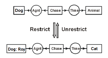
Figure 5
Figure 5 shows a conceptual graph that represents the sentence “A dog is chasing an animal”. By applying two restrict rules, the conceptual graph has been modified to a new sentence: “The dog Roy is chasing a mouse”. The concept [Dog} dictates that there is some dog and this concept is restricted by the referent making the concept more specific - [Dog: Roy], which says that a dog named Roy exists. The next step shows that there exist the concept [Animal] and It is restricted to the subtype concept [Cat]. The more generalized graph is implied by the more specialized one, giving the result if the dog Roy is chasing a cat, then a dog is chasing an animal.
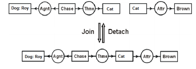
Figure 6: Join and Detach
The two conceptual graphs on the figure 6 represent sentences “Roy is chasing a cat“ and “A cat is brown”. Two equal copies of the [Cat] concept are overlaid by the join rule and build a single conceptual graph to describe the sentence “Roy is chasing a brown cat”. Oppositely to the join rule, the detach rule disjoins the graph and creates two graphs. In the given example, detach brings us to the initial two graphs. To represent the given graphs in the CGIF sentences, the following structure is used:
Sources
http://www.jfsowa.com/cg/cg_hbook.pdf https://en.wikipedia.org/wiki/Conceptual_graph http://www.jfsowa.com/cg/cgexampw.htm


